



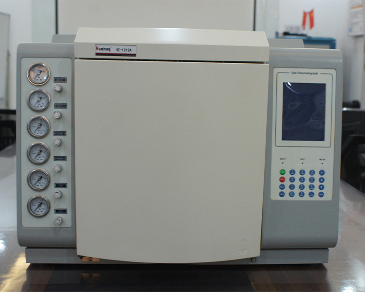
The correct connection and regular leak detection of the gas circuit system are the foundation of safe operation in the daily use and maintenance of gas chromatographs. The HZGC-1212A manual extensively emphasizes gas safety, especially the use of hydrogen, for a very direct reason - hydrogen is a flammable and explosive gas, and leakage into a sealed column box may cause an explosion when exposed to high temperatures.
Composition of gas path and pressure requirements
The pneumatic system of HZGC-1212A consists of three channels: carrier gas, hydrogen gas, and air, each with clear requirements for input pressure:
Carrier gas (N ₂ or He): 343-392kPa (approximately 3.5-4.0kgf/cm ²)
Air: 294-392kPa (approximately 3.0-4.0kgf/cm ²)
Hydrogen gas: 196-392kPa (approximately 2.0-4.0kgf/cm ²)
The initial stabilizing valve inside the instrument has been strictly calibrated at the factory (usually set at about 0.35MPa), and cannot be adjusted by oneself. Changing it without authorization will result in inaccurate control of gas path pressure and affect the reproducibility of analysis.
Strict sequence of hydrogen usage
When using a FID detector, hydrogen gas is required, but the opening of hydrogen gas must follow a strict sequence:
Install the color spectrum column
Connect all connectors of the injector and detector properly
Perform leak testing on all connections to confirm that there are no leaks
Only after confirming everything is normal can the hydrogen gas source be turned on
It is absolutely forbidden to open the hydrogen valve when the chromatographic column is not connected or the connector is not tightened - hydrogen will accumulate inside the column box, and once it reaches explosive concentration and encounters high temperature or sparks, the consequences will be unimaginable.
Standard leak detection process
After the installation of the external air circuit is completed, leak detection should be carried out according to the following steps:
Step 1: Close all voltage stabilizing valves and flow stabilizing valves on the host; Step 2: Open the main valve of the steel cylinder and slowly adjust the pressure reducing valve to make the low pressure gauge indicate about 3kgf/cm ²; Step 3: Close the high-pressure valve of the steel cylinder and observe whether the low-pressure gauge reading drops.
If the low pressure gauge indicates a continuous decrease, it indicates that there is a leak in the external air circuit. Soap solution (neutral soap water) must be applied to all joints section by section, and the leak must be found and repaired before re leak detection. Subsequent operations can only continue after passing the leak detection.
Operation taboos for steady flow valves and needle valves
It is not advisable to fully rotate the pneumatic control valve when it is closed - excessive tightening can damage the sealing components inside the valve, leading to premature scrapping of the valve components. Stop when there is slight resistance when reaching the closed position, do not forcefully tighten.